
Nomenclature
 I'm a real stickler for naming conventions accurate and consistent - probably because I'm so easily confused! There is another good reason, though. I always want to know, not only how something works, but why, as often as we design parts and components. When you are preparing your own hybrid shaft, for example, suddenly becomes very important to understand whether the part # 46 in the diagram is indeed an oil-deflector, a board or a thrust washer - because all three are very different roles. The parts counter guy does not know or care what the difference is that the five manuals and parts books could be called something slightly (or completely) different - but it will be very important to you because the case where and how to use one in your custom axis will depend entirely on your understanding of what the part really is and what it does. Having said that - I understand that some of the terms used are so well entrenched, even though it might not be 100% technically correct, to use any other term just cause more confusion. Sometimes there are two or more correct terms for the same thing, so in order to keep things as clear as possible the following drawings and diagrams illustrate the terms used in this article.
Nomenclature ring gear
Key:
A - Top. The top of the gear tooth, aka Face, Top Earth
B - Root. The bottom of the gear tooth, aka Edge
C - Heel. Outside-diameter end of the gear tooth
D - Toe. The inner diameter end of the gear tooth
E - Drive. The convex side of the gear tooth *
F - Coast. The concave side of the gear tooth *
* Do not be fooled by the terms "cost" and "unity" as the ring gear can be driven by the pinion on both sides of the teeth. Which side of the teeth depends on whether the game is standard spiral gear or reverse and if the vehicle is moving forward or backward.
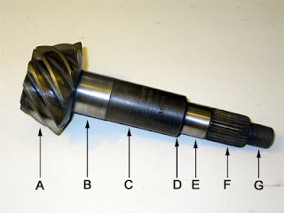
Nomenclature Pinion
Key:
A - Head
B - Interior of the bearing seat
C - Shaft
D - Shoulder
E - Outside bearing seat
F - Splines
G - Topics
Nomenclature gear mounting
Key:
A - Pinion Nut
B - Pinion Nut Washer
C - Yoke (aka Yoke end or flange)
D - Pinion Oil Seal.
E - Thrust Washer
F - Foreign pinion support
G - Wedges external gear (also known as pinion preload shims)
H - pinion carrier deflector
I - The wedges internal gear (also known as shims pinion Depth)
J - Interior pinion support
K - slinger inner pinion
L - gear (gear or pinion gear alias)
Figure 4 - Nomenclature Carrier
Key:
A - Housing (aka pork, pumpkin, Chunk, Section Centre) *
B - ring gear (crown gear alias)
C - Carrier (alias differences, differential box) *
D - Cap Carrier-bearing
E - Wedges Carrier-bearing (aka Diff bearing wedges)
* Please note that, technically, Dana / Spicer refer to Part C as "Case - Differential" or simply "case" and part A as the "carrier." However, most of us have been calling C the "Carrier" (and therefore D ball carriers and others) for so long that I will stick to avoid confusion.
In describing the different bearings on the diff, I will use the term "influence" as a set of two pieces, "cup" in the sense of the race itself and "cone" to indicate only the support roller .
Theory
OK, so we know that creating gears requires care and precision, but the whole process is really a matter of adjusting four different configurations but related until they all fall within specifications. The four values are:
Backlash
Reaction
Definition: The amount by which a tooth space than the thickness of a cog.
Think of it as: Play between mating teeth of the gears or force the ring gear and pinion gear.
 How to measure: Measure the free movement of the pinion gear rings remained stable, in mils, with a dial indicator on the ring gear. In other words, you are measuring how much you can turn the ring gear before engaging the sprocket teeth - this is the space between the teeth - called 'backlash'.
Adjusted Via: Carrier shims. Adding wedges on the side of the gear ring carrier ring moves closer to the pinion gear, causing the teeth engage more closely, decreasing the amount that the ring gear can swing without rotating the pinion , and therefore the decrease of the reaction. Adding wedges on the side not ring gear ring gear moves away from the sprocket, increasing reaction. Please note: carrier added wedges aside must be subtracted from the other, and vice versa, to maintain a consistent carrier pre-load.
Note: Changes Backlash about 0.007 "for each 0.010", the carrier moves. In order to have reaction (ie the ratio gears are not tight configuration, clearance) is to prevent the gears from jamming together. The lack of reaction may cause noise, overload, overheating, or seizure and failure of the gears or bearings.
Pinion Depth
Definition: Position-pinion gear to the axis of the ring of gears, expressed either as a mounting distance (measured from behind the head of the sprocket to the centerline of the ring gear) or a remote control (measured from the face of the head of the pinion to the center line of the ring gear).
Think of it as: How close is the head of the pinion to ring gear shaft. Ensures adequate depth pinion gear teeth mesh with half of the teeth on the ring gear - between the top and the root. Increasing the depth of the pinion moves the pinion closer to the centerline of the ring gear, moving the pinion "deeper" into the ring gear teeth and reducing the distance checking.
 How Measured: The final determination of the correct pinion depth can only be obtained by reading and interpreting the pattern of tooth contact using the compound gear brand. There are specialized tools to measure pinion depth, but they are expensive, they are not necessary, and are used to calculate the starting point - final proof is always in contact pattern.
Adjusted Via: inner pinion shims located between the housing and the pinion inner bearing cup. Adding wedges pinion moves closer to the center line of the ring gear, moving the upper pattern of the root. Extraction wedges pinion moves further from the axis of ring gear, the pattern moving from the root to the top.
Note: When setting the pinion depth, start with a wedge starting stack and make adjustments in the first (10-20 milliseconds) until the correct setting is in brackets, then make smaller and smaller adjustments until it reaches final adjustment. Adding or subtracting one wedge one you can, and does, make a difference. Increasing pinion depth also decreases the reaction pattern unit moves slightly toward the bottom, and the coast pattern slightly toward the heel. Reduce pinion depth also increases the ease and pattern moves slightly towards the heel unit, and coast pattern slightly to the toe. Increasing the depth of the pinion also increase pinion bearing preload unless modified outer pinion wedges.
Pinion bearing preload
Definition: Bearing preload is a measure of rolling resistance in a bearing or "bearing stiffness." As a cone is pressed against his cup, the point or line of contact between the roller and the cup is made larger, increases friction and preload is said to be higher. Correct bearing preload is a compromise between stiffness and resultant wear bearing preload.
Think of it as: How are pressed firmly into their cups and both are to be rigidly rotating pinion bearing cones.
How Measured: A torque wrench inch pounds used pinion nut to measure the torque required to rotate the pinion installed.
Adjusted Via: Outer pinion shims placed between the face of the cone outer pinion bearing and the shoulder on the pinion shaft. Adding supplements causes pinion bearings are separated from their cups, reducing preload and vice-versa. Add shims to reduce preload and remove shims to increase preload.
Note: pinion preload is usually specified without axles or shafts installed, with the yoke and pinion nut torque spec installed but installing any pinion seal. A vehicle installed can add 2-4 inches-pounds and a new oil seal adds approx. 3 in-lbs. Preload decreases little capacity as bearing surfaces between the roller and the cup is reduced. Preload excess friction increases, resulting in excessive noise, heat and rapid wear.
Carrier-bearing Preload
View pinion bearing preload: Definition
Think of it as: How are pressed firmly into their cups and both are to be rigidly rotating cones bearing support. It also controls the force holding the housing company.
How Measured: You can not measure directly.
Adjusted Via: When you add or subtract a number of spacers equal weight bearing on both sides of the vehicle. Ideally, the total stack media wedge (sum of both sides) should be approx. 0.015 greater than the available space, and a spreader case be used. "However, if a spreader is not critical, and a good approximation of the carrier bearing preload may be in the verification of the carrier can only be installed with a good blows of a hammer blow.
Note: If the preload is too little support, the carrier moves away from pinion under load (squirm or deflect), increased reaction. This could lead to insufficient contact of the teeth, resulting in chipping / breakage of the gear teeth.
dial indicating torque wrench inch pounds
Tools
You need a good complete set of regular hand tools, including hammers usual drills, socket wrenches, and the like. Air tools are not a necessity, but it certainly will do the job much faster and easier. You also need the following:
Foot pound torque wrench - you need to be able to read at least 250 pounds-feet of torque pinion nut, which affects the pinion bearing preload. You can try to do without, and use a "calibrated feeling" cheater bar or an impact wrench, but you seriously harm your startup does.
Inch-pound torque wrench - required reading for pinion bearing preload. The "experts" sometimes claim to be able to establish this by touch. Those who have a lot of experience or a touch can probably gifted - but it is not a recommended method for most. Of course, I can not and do not want to be without this tool - again, it directly affects one of the four core values we are trying to do it right. Because you have to use the tool to measure torque while rotating the pinion, a "click-style" torque wrench does not work - must use a beam style or better yet, a line indicating a torque wrench. Figure 7 shows the unity of a quarter inch Armstrong, 0-75 in-lb model convinced me, despite its cost about $ 300. I understand that beam type keys can be purchased for much less at bike shops.
Dial Indicator - necessary to measure the run-out, backlash, and carrier shim stacks. It might be possible to get backlash about just by reading the contact pattern, but with specifications in the range of between four ten thousandths of an inch, you will get a hard enough job without a dial indicator.
0-1 "micrometer calipers - necessary for measuring shims old and new. You just can not do the job without it.
Tuning bearings - to avoid damaging real bearings and / or going crazy while pulling and pressing the bearings and off a dozen times or more is very likely have to make adjustments to batteries wedges. Take my advice - do not even think about work underway undefined bearings. In addition, you can easily make your own bearings development of the old bearings - which also gives you all the reason you need to use when creating new bearings gear - something I recommend anyway.
Gear marking compound and brush - to read the contact pattern of the teeth, the most critical part of all the work - you simply can not do without it.
Extractors bearings and / or bearing spacer with a press. Depending on their size, have one or both of them to remove the old cones pinion bearings and carrier. I've seen people try to work with hammer and punch (ahem, cough) and the results are predictably disastrous. Do not ask why I have a big pile of bearings in ruins in the corner, please!
Drivers and / or release bearing / seal - right drivers are required to install the support cones leading into the company (a press is preferred, but can be done carefully with a hammer and driver), pinion cups in the housing (a driver must be used), and cone bearing on the pinion (press preferred for inner bearing cone-pinion steering, the driver must use outdoor). You can often make their own drivers, or at least the shafts, waste pipe or tube, but the face should be soft (aluminum or brass) to avoid damaging the new bearings.
Sprocket-nut socket - 15/16 "is necessary for making 60 Dana sprocket nut with a wall thin enough to fit on the yoke.
Pry bars - required to remove the carrier housing in most cases. A spreader case would be better, but not essential.
Recoilless hammer - needed to seat the carrier and / or the pinion in the housing, especially if you use a case spreader. A hammer blow is a combination of a mallet and a hammer: heavy as a soft-faced hammer as a hammer to avoid damaging components. It also has a moving weight inside to reduce the "bounce" when struck (hence the name "thud").
Punch or stamp - to mark the limits of supporting carrier so they can re-install properly.
Variety of keys, sockets, screwdrivers, oil drain pan, RTV silicone, thread locker, vice, hammers, parts cleaner, rags, and a breaker bar 3 feet or overall impact wrench.
Step by step procedure
Before beginning this, or for that matter any work on your computer, make sure you have and actually use adequate security, especially protective equipment for eyes. It is not just a legal requirement lame that makes me say that - is the fact that I have a synthetic lens in my left eye and most painful memory of a piece of steel wire half inch sticking in my eyeball. So use your computer, right?
There are four main phases in the creative work of the gears. They are:
Disassembly, cleaning and inspection
Preparation and calculation starting batteries wedges
Installation and set-up adjustment bearings
The installation of new bearings, assembly and final testing
Dismantling
Disassembly is simple. If not completely sure at this point, might be a good idea to consult a manual or have a friend help - if only for moral support. Personally, my friend likes to be around and do what he imagines are sure witty comments while drinking my beer. I will not mention names to protect the guilty - but 3D technical drawings more amazing! I of course replied, causing tooth count ring and pinion and old bolts cleaned with a toothbrush! Having said that, the following points are noteworthy:
- You can set up the gears with the shaft in the vehicle, but is a pain. I recommend that you remove the front axle. If you leave it in the vehicle, remove and reinstall the gears while adjusting wedges becomes a PITA such that you are responsible for lose patience and compromise your setup.
- Be sure to check the caps bearing support with a punch so they can re-install on the exact location and orientation as they were originally.
- When removing the stand and pinion ensures that the label all wedges, bearings, screens and washers with their place of origin, orientation and dimensions.
- When you drive the pinion of the box, not to break the thread of great big hammer - use a brass drift. However, do not get so distracted thinking about how smart you are to have thought of this for once with joy to drive pinion box to see only four meters and break down in the concrete floor!
Preparation
First, gather all the tools and parts, clean place to work, and then clean and inspect all components, including new. You need to remove the protective layers or packaging waste and is not unknown for new bearings or shims have flaws, and now is the time to find out if they do. You should also take the time to measure all new wedges with the micrometer and label each with fine-point permanent marker. This will make the job much easier adjustments. I recommend starting with a good master quality installation kit and always use new bearings - it's cheap insurance and gives peace of mind. You should also never reuse a pinion nut and ring gear bolts. I have a preference for Dana / Spicer gears and equipment commissioning and Timken bearings but there are other good quality components. I would, however, recommend avoiding the Motive Gear install kits as they give an inadequate number of supplements, and included, according to my measurements, dimensions come in strange and confusing as 12.4, 14.8, and 16 500 , compared with the Dana wedges that I used were all standard as 3, 10 and 20 mil, and varied no more than 0.0001 ".
Figure 8 - Master installation kit contents
A main kit to complete installation containing all you need to include:
Gear marking compound
Pinion crush sleeve (if necessary)
Pinion Nut
Ring gear bolts
Pinion inner bearing and outer pinion shims
Exterior and inner pinion bearings
Ball bearing
Pinion seal oil
Many also include some cheap thread locker and RTV silicone gasket making, which usually throw away in favor of my favorite brands. The state of the old pieces will determine whether you need to purchase any required slingers, screens and thrust washers. Depending on whether you are starting with a complete set of shaft or box collection naked and used parts, this can be a bit confusing.

0 Komentar untuk "Ring&Pinion Nomenclature "